|
Technical
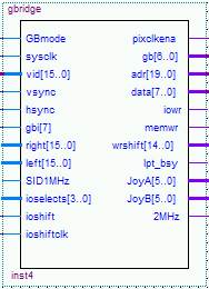 GBmode: Selects one of two graphics modes, and can be toggled dynamically. low: 25 Mhz pixel clock mode with 65k colours (hi-colour) high: 33,8Mhz pixel clock mode with 4096 colours (only upper 4 bits of digital RGB values, like Amiga-OCS) sysclk: connect to 101Mhz board clock, that's pin 79 of the 1k100. vid 15..0: These are the binary video bits, mapped as follows: vid[15..11] = blue[4..0] vid[10..5] = green[5..0] vid[4..0] = red[4..0] Note that in 33,8 Mhz pixel clock mode, vid[11, 6, 5, 0] are unused and should be set to 0. vsync, hsync: inputs to the gbridge, should be VGA frequencies, but can be any scan rate, because they're passed to the monitor directly. pixelclkena: Output, this is the pixelclock that the gbridge generates. The name might be a bit confusing, as it can also be used as a clock_enable for the board clock, but it has turned out to be more stable to use this as an async clock. Pixels are sampled on the falling edge of the signal. In 25 Mhz mode, the signal is 25% high, and 75% low, while in 33Mhz mode, the signal is 33% high, and 67% low. gb[6..0], gb[7] This is the graphics bus, just connect to the respective pins of the 1k100. The reason why gb[7] is in a different place is that the signal plays a special role in the protocol - just ignore, you can't change very much on the protocol anyway ;-) right[15..0] and left[15..0] These are the audio signals that are sent to the CD audio DAC. Just connect your binary audio signal to these lines. At this point, there's no way for you to find out when the word is latched. Please sync your audio source to the 2Mhz signal, as 48 clocks are used to clock the data into the DAC (resulting in exactly 44,1khz audio). A later version will make the LRclock available to the 1k100 design, so you can sync your source to the DAC. SID1Mhz: Input to gbridge. This signal is routed to the SID directly, delayed by about 20 to 60ns (25 Mhz mode) or 20 to 80ns in 33Mhz mode. This eases syncing the SID chips to the 1k100 design, and it's for giving the chips the most precise clock that you can generate out of the base clock. Note that the SID derives all tones from this clock, so the differece between PAL and NTSC clock makes a huge difference to the human ear - even to those who are not very audio-phile! ioselect[3..0] These signals are for accessing the IO stuff of the C-One, like IDE, clockports, flashrom and all the other stuff (see schematics). Data can be read/written on the mdb[7..0] bus. Bit combinations are like this: 1111 sets all signals high (default) 0111 unused 1110 IOW 0110 IOR 1101 IDE2 write 0101 IDE2 read 1100 IDE1 write 0100 IDE1 read 1011 FDC write 0011 FDC read All other combinations are unused, please don't use, as we might need them for future enhancements. If you want to access things that use IOW and IOR, you have to set the csel[] signals properly *before* sending the respective signal to the 1k30. Accessing the FDC means that you're talking to the emulated NEC765 chip of the early startup core. This can be used to add a NEC765-based floppy drive emulation to your core. The early startup is still running in the background, and the floppy emulation runs at the same time. A command list with the additional commands that load a disk image will be added later. ioshift, ioshiftclk: Please connect to the respective pins - these are necessary for the communication with the 7064 CPLD, which has most of the IO connections like joystick and LPT bus. adr[19..0], data[7..0], iowr, memwr These lines are for transferring rom images during early startup, and for having a connection between the Z80 processor of the early startup to possible periphals in the 1k100. On a memory-write, the address and data lines reflect the location and contents of the memory cell. The actual write is initiated with a low pulse of memwr. Same applies to iowr, with the difference that iowr goes low for IO accesses of the Z80 processor. wrshift[14..0] These are internal signals of gbridge that are used to time the release of iowr or memwr. Just ignore if you don't want to change the timing of these signals. If you want to, have a look at the source! lpt_bsy and joystick signals: JoyA[5] Joystick port A FIRE1 (normal fire) signal, active-high JoyA[4] Joystick port A FIRE2 (right mouse button) signal, active-high JoyA[3] Joystick port A RIGHT signal, active-high JoyA[2] Joystick port A LEFT signal, active-high JoyA[1] Joystick port A DOWN signal, active-high JoyA[0] Joystick port A UP signal, active-high JoyB[5] Joystick port A FIRE1 (normal fire) signal, active-high JoyB[4] Joystick port A FIRE2 (right mouse button) signal, active-high JoyB[3] Joystick port A RIGHT signal, active-high JoyB[2] Joystick port A LEFT signal, active-high JoyB[1] Joystick port A DOWN signal, active-high JoyB[0] Joystick port A UP signal, active-high The lpt_bsy signal comes directly from the centronics port. Not inverted! The 2Mhz signal is an output from gbridge. This is the 2Mhz signal that is used for communication with the Audio DAC, and is transferred by gbridge into the 1k100. There's a small phase shift between this 2Mhz clock and the real clock that is routed to the DAC, it's the same as with the 1Mhz SID clock: delayed by about 20 to 60ns (25 Mhz mode) and 20 to 80ns in 33Mhz mode. There is no correlation between the 1Mhz SID clock and the 2Mhz DAC clock! The delay for one of the signals can be 20ns, while it can be 60ns for the other. Also note the the 2Mhz signal is a 2,1168Mhz - if you want to be precise ;-) The joystick and lpt_bsy signals are part of the shift-register communication with the 7064 CPLD. If the ioshift signal is only used by the 1k100, the ioshiftclk can be any clock, as long as it's connected to pin 168 of the 1k100. ioshiftclk is available on the 1k100, but not on the 1k30. However, the 1k30 needs access to the joystick signals in some cases (mainly the CPC cores), so it needs to have some syncronity on the ioshift signal. This can ONLY be achieved by connecting the 2Mhz signal of gbridge to the ioshiftclk signal and to pin 168 of the 1k100 (which goes directly to the clock pin of the 7064). |